Project: To create real-time pen and ink illustrations using 3d polygonal models. This was done following some ideas from papers written in the past with some ideas of my own to keep it from becoming too slow. The project was implemented as a final project for the last two weeks of my undergraduate graphics class at the University of Utah in the spring of 2001.
Related Work: Most of my implementation comes from ideas in Computer-Generated Pen-and-Ink Illustration by Georges Winkenbach and David H. Salesin from the 1994 Siggraph Computer Graphics preceedings. In this paper they discuss the different brush strokes and tones used to create textures that can be applied to a model to create a pen-and-ink look.
Another paper that I got some of my ideas from was Illustrating Smooth Surfaces by Aaron Hertzmann and Denis Zorin from the 2000 Siggraph Computer Graphics preceedings. They show how to achieve good silhouette edges in your images and following the contours of your surface to get the curvature of the model in your image(which I have not done).
Goals: I have always had an interest in creating computer-generated images that imitate traditional artistic styles. My original goal was to write a program that would act as a base for further study by implementing some basic ideas in the area of pen and ink illustrations. Upon reading many of the papers and research that was done I found that I really liked the images that were being created, but I didn't like the complexity nor the render time for most of these methods. I wanted to write something that would be interactive, ie. changing the texture, model, model orientation, and light orientation in real-time.
Implementation: To begin the project I wrote a basic OpenGL program to display a model with rotation balls for the model and the lights. The next step was to create silhouette edges. This was done by taking the dot product of each vertex with the eye vector and if one of the vertices in a triangle had a positive dot and one had a negative dot then draw the triangle. This gave some pretty good results but you could not really see the triangles that were on the side so I repeated the silhouette draw in line mode so that it became dark enough. To get rid of backfacing silhouettes I had to draw the model in the depth buffer with polygon offset turned on before drawing the silhoutte triangles. This seemed to give me decent silhouttes, but more work could be done in this area.
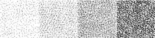
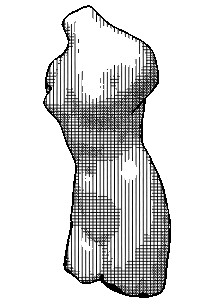
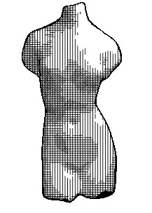
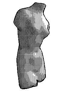
Next I needed to apply the pen-and-ink look to the model by using several layers of textures. I got the idea from the Winkenbach/Salesin paper to create a set of textures differing in tone from light to dark. I started with three stipple textures because I decided that a stipple would not give any type of directional problems when applied directly to a model. The three textures varied in tone from light to dark tones and were created using 3DPaint. I wanted to split my model into contours much like a topological map and apply the textures in levels. I had several ideas to do this: First, I could use the depth buffer and split it up into regions; Second, I could create a light map and split that into appropriate regions using the color; and third, to somehow use the geometry of the object itself to find contours. After doing the silhouette edges, I decided I could use a similar algorithm to do it the third way. I took the light source did a dot product with the facet normal for each triangle to get a value between -1.0 and 1.0. I then split this region up about the way a specular light would and applied the textures in layers to these contours. The algorithm is described in more detail below.
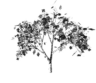
At this point I saw some results that looked pretty good and I was relieved to discover that my underlying assumptions were valid. There were several problems that I encountered though, almost all of the models that I had been using were lacking texture coordinates, and the three textures did not seem enough to create a smooth gradient. To remedy this, I created a couple of simple models and made several more textures--cross hatch, scribbles, and paper(not really a pen-and-ink texture, but it looks good anyway). These textures are shown below. Upon applying the cross hatch texture to the models I became somewhat discouraged because there were considerable banding artifacts that would appear because of the uniformity of the texture. To remedy this and the problem I was having finding decent models with texture coordinates I came up with an idea to project all of the triangles in the model to the screen and using these 2d points as texture coordinates. I was very pleased with the results that this gave me, it cleaned up all of the banding artifacts plus it had the added benefit of creating texture coordinates for the models that did not have them. This did slow down the frame rate a little because now I am doing these projections every time I draw, but it does not seem to be too bad. The negative side to this is that it removes any contour information that I had when texture coordinates were in 3d and wrapped around the model. I felt that the pros were greater than the cons however, so this is what became my final result.
Future Work: This project is far from complete. I consider it a base for further study and research. Some of the areas that I feel could be improved are silhouettes, textures, shadows, and contours.
A better algorithm for creating silhouettes is described in the Hertzmann/Zorin paper cited above. They describe a more complicated way to get internal, more complete and cleaner looking silhouette edges.
Another area that could be improved upon is multiple textures per scene. An example of this is in the Winkenbach/Salesin paper where they use one set of textures for brick, another for wood, and yet another for grass all in one scene.
The addition of shadows would also give the images a better feeling of depth. This could be done pretty easily with a ground plane under the object and projective hard shadows as described in the red OpenGL book.
Finally, an area that I feel my project is lacking would be the following of contours in the model to give the image more depth. The Hertzmann/Zorin paper does of great job of describing this in detail. I think this would be a more difficult addition but the result would look much better.
Algorithms:
Silhouette Edges:
disable color buffer
enable depth buffer
enable polygon offset
draw every triangle
disable polygon offset
enable color buffer
set polygon mode to line draw
set line width
for every triangle
n1 = vertex 1 normal
n2 = vertex 2 normal
n3 = vertex 3 normal
v1 = viewpoint - n1
v2 = viewpoint - n2
v3 = viewpoint - n3
dot1 = dot(n1, v1)
dot2 = dot(n2, v2)
dot3 = dot(n3, v3)
if ((dot1 > 0 and dot2 < 0) or (dot1 > 0 and dot3 < 0) or
(dot2 > 0 and dot1 < 0) or (dot2 > 0 and dot3< 0) or
(dot3 > 0 and dot1 < 0) or (dot3 > 0 and dot2 < 0))
then draw the triangle
Texture Layers:
for i = 0 to 3
set texture to tone i
for every triangle
n = facet normal
l = lightposition-vertex
normalize(n)
normalize(l)
dot = dot(n, l)
if (i = 0)
then if((dot < 0.7) and (dot > 0.4))
then project vertices to 2d
set texture coordinates to 2d projection
draw triangle
if(i = 1)
then if((dot < 0.4) and (dot > -0.1))
then project vertices to 2d
set texture coordinates to 2d projection
draw triangle
if(i = 2)
then if((dot < -0.1) and (dot > -0.3))
then project vertices to 2d
set texture coordinates to 2d projection
draw triangle
if(i = 3)
then if(dot < -0.3)
then project vertices to 2d
set texture coordinates to 2d projection
draw triangle
Interface: The interface is done using Paul Rademacher's GLUI user interface which can be found here. This is a list of the options I implemented.
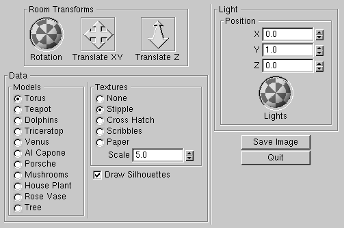
Room Transforms - Rotate, and translate the object in x, y, and z diffections by dragging the icons with the left mouse button down. These same transforms can be accomplished using the left, middle, and right mouse buttons respectively in the object screen.
Models - A list of wavefront .obj model objects are listed in the radio box. Selecting one of these buttons will change the object displayed in the main window.
Textures - Each button will enable a set of textures with the given name. Each is a set of 4 tones that will create 5 layers on the object in the main window(including white). The "None" option will not put any texture on the object.
Scale - The texture scale spinner will scale the textures displayed in the main window. The larger the scale the smaller the texture will appear. The texture size is dependent of the window size so by shrinking the window, your texture will appear smaller and in some cases will cause unwanted visual artifacts. This can be fixed by setting the scale to a smaller number. The default is 5.0 and is applied in the x and y directions.
Draw Silhouettes - This checkbox will enable and disable the silhouette edges that are being drawn. Depending on the model, this may give you a better image.
Light Position - The light position will arrange where the light is located. Dragging the arcball with the left mouse button down will rotate the light around the scene and update the texture on the object interactively. The light position is set at the first and by rotating it will make these invalid. Synching the spinner and the arc ball still needs to be implemented.
Save Image - When this button is pressed an image will be written out to the current directory. The image is in the .ppm format and will be saved as image.ppm. These images are uncompressed and very large so it may take a while depending on the size of your window. PPM files can be read using The Gimp on Linux or XV on Unix machines.
Quit - Exits the application.
Source and Binaries:
To compile you must have the glui libraries you can find here
Unix source - ink_full.tar.gz
Sgi binaries - ink_sgi.tar.gz
Linux Red Hat binaries - ink_linux.tar.gz
Windows source - ink_win_full.zip
Windows binaries - ink_win_bin.zip
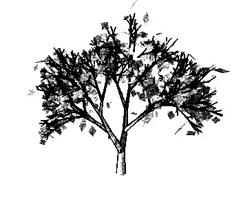
Image Gallery:
Textures
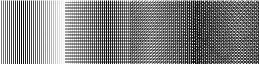
Cross Hatch
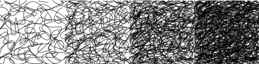
Scribbles
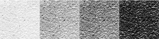
Paper
Generated Images:
Rotation of Object
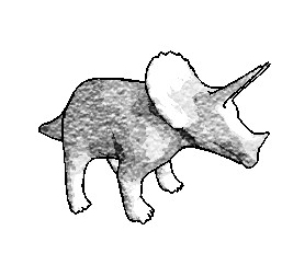
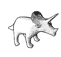
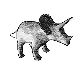
Rotation of Light
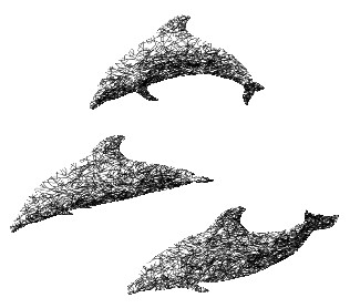
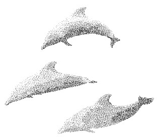
Different Textures
Silhouettes On and Off
Steven Callahan
stevec@sci.utah.edu
last updated 4/27/01